What Is the SunFounder GalaxyRVR and Why Assemble It Correctly?
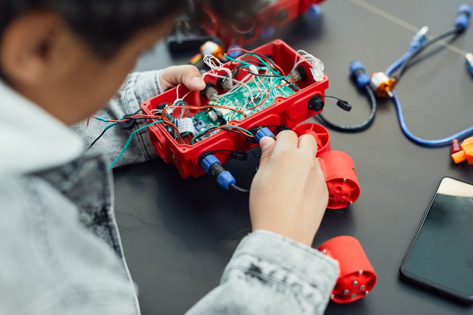
The SunFounder GalaxyRVR is an Arduino-based Mars rover robot kit designed for STEM education. It combines mechanical assembly with programming skills to teach robotics fundamentals. Proper assembly ensures smooth operation, prevents component damage, and maximizes learning outcomes. The kit includes motors, sensors, wheels, and an Arduino microcontroller board. Correct assembly takes 45-90 minutes for beginners. Following the official manual step-by-step prevents frustration and costly mistakes.
Assembly quality directly impacts the rover’s performance and your learning experience. A well-assembled GalaxyRVR runs smoothly, responds accurately to commands, and survives repeated testing. Poor assembly can cause misaligned wheels, loose connections, and sensor malfunctions. This guide walks you through every phase with clarity and precision. Whether you’re a student, educator, or hobbyist, careful assembly builds confidence and competence in robotics.
Key Takeaway: Proper assembly of the SunFounder GalaxyRVR ensures optimal performance and a solid foundation for learning Arduino robotics.
What Components Come in the SunFounder GalaxyRVR Kit?
The GalaxyRVR kit includes all mechanical and electrical components needed to build a functional rover. Understanding each part before assembly prevents confusion during construction. The chassis forms the robot’s body, while motors drive the wheels. Sensors detect obstacles and environmental conditions. The Arduino-compatible microcontroller board processes commands and controls movement. Wiring harnesses connect everything together. Fasteners like screws and brackets hold components securely in place.
Here are the primary components you’ll work with:
- Plastic chassis frame (body structure for the rover)
- Four DC motors with gearboxes (drive the wheels)
- Four wheels with rubber tires (enable movement)
- Arduino-compatible control board (brain of the robot)
- Ultrasonic sensor module (detects obstacles ahead)
- Line-tracking sensor (follows dark lines on surfaces)
- Motor driver module (controls motor power and direction)
- Battery holder and rechargeable battery pack (power source)
- USB cable and jumper wires (connections and programming)
- Screws, brackets, and fasteners (assembly hardware)
Organize all components on a clean workspace before starting. Check the official SunFounder website for a detailed component checklist. Missing parts should be reported immediately for replacement.
Key Takeaway: Familiarizing yourself with all kit components before assembly prevents delays and ensures nothing is overlooked.
How Do You Prepare Your Workspace for GalaxyRVR Assembly?
A well-organized workspace speeds up assembly and reduces errors. Choose a clean, flat, well-lit table or workbench. Ensure adequate space—at least 2 feet by 2 feet—for laying out parts and working comfortably. Good lighting prevents missed connections and helps you see small components clearly. Remove clutter and distractions to maintain focus during the 45-90 minute assembly process.
Gather these tools before you begin:
- Phillips head screwdriver (for fastening chassis and components)
- Small flashlight or headlamp (improves visibility in tight spaces)
- Tweezers (helps place small jumper wires and connectors)
- USB cable for programming (connects board to your computer)
- The official assembly manual or video guide (reference during work)
- Small container for screws and small parts (prevents losing fasteners)
Lay out the assembly manual or open the SunFounder video guide on a nearby screen. Keep the official documentation visible throughout assembly. This reference prevents mistakes and clarifies any unclear steps. Test your lighting by simulating how you’ll see the smallest components during work.
Key Takeaway: Proper workspace preparation and tool gathering save time and prevent assembly mistakes.
How Do You Assemble the GalaxyRVR Chassis and Motor System?
The chassis assembly forms the physical foundation of your rover. Start by identifying the main plastic chassis frame—it’s the largest component. This frame holds the motors, wheels, and sensors. Attach the four motor brackets to the chassis using the provided screws. Ensure brackets are aligned symmetrically on all sides. Misaligned brackets cause uneven wheel alignment and poor movement.
Attaching Motors to the Chassis
Each DC motor with gearbox mounts into a bracket on the chassis. Slide the motor into its bracket carefully, ensuring the output shaft aligns with the wheel mount. Secure each motor with two screws—don’t over-tighten, as this can crack the plastic bracket. Check that all four motors sit flush against their brackets. Loose motors cause vibration and poor performance.
Follow this sequence for motor installation:
- Insert the motor into the front-left bracket first, securing with two screws.
- Move to the front-right bracket and repeat the process.
- Install the rear-left motor, ensuring alignment with the front motor.
- Complete the rear-right motor installation, checking all four motors are level.
- Test motor shafts by hand—they should spin freely without resistance.
Installing Wheels and Connecting Motor Shafts
Wheels attach directly to the motor output shafts. Each wheel has a central hub that slides over the shaft. Push wheels firmly onto shafts until they sit snugly. Use the small set screws provided to lock wheels in place. Verify wheels are perpendicular to the chassis—tilted wheels cause the rover to veer off course.
Spin each wheel by hand to confirm smooth rotation. The wheel should turn freely without grinding or resistance. If a wheel binds, check that the motor shaft is straight and the wheel hub isn’t cracked. Properly installed wheels are critical for straight movement and obstacle navigation.
Key Takeaway: Careful motor and wheel installation ensures balanced movement and prevents early component failure.
How Do You Connect the Motor Driver and Power System?
The motor driver module controls power delivery to the four motors. This module receives commands from the Arduino board and translates them into motor movements. Proper wiring prevents short circuits and ensures safe operation. The motor driver typically mounts on top of the chassis using double-sided tape or brackets. Position it centrally for balanced weight distribution and easy access to connectors.
Wiring Motors to the Motor Driver
Each motor has two wires—positive and negative. These connect to the motor driver’s output terminals. The motor driver has four output channels: two for front motors and two for rear motors. Connect front-left motor to channel 1, front-right to channel 2, rear-left to channel 3, and rear-right to channel 4. This standard configuration simplifies programming later.
Motor wiring checklist:
- Front-left motor → Motor Driver Channel 1 (both wires secure)
- Front-right motor → Motor Driver Channel 2 (both wires secure)
- Rear-left motor → Motor Driver Channel 3 (both wires secure)
- Rear-right motor → Motor Driver Channel 4 (both wires secure)
- All connections tight and insulated from chassis metal parts
Installing the Battery and Power Connections
The battery pack powers both the motor driver and Arduino board. Mount the battery holder on the rover’s underside or rear using brackets. Connect the battery’s positive wire to the motor driver’s positive input. Connect the negative wire to the ground terminal. Never reverse polarity—this damages components instantly. Use a battery connector with a switch for safe on-off control.
Connect the motor driver’s power output to the Arduino’s power input using jumper wires. This supplies power to the microcontroller. Double-check all power connections before inserting the battery. Loose power connections cause intermittent failures and frustrating debugging sessions.
Key Takeaway: Correct motor driver and battery wiring ensures safe power delivery and responsive motor control.
How Do You Install and Wire the Sensor Modules?
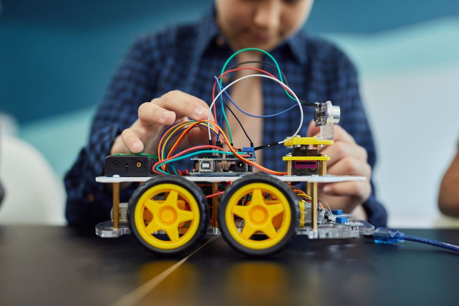
Sensors give the GalaxyRVR awareness of its environment. The ultrasonic sensor detects obstacles ahead, while the line-tracking sensor follows dark lines on surfaces. Proper sensor placement and wiring enable autonomous navigation. Mount the ultrasonic sensor on the front of the chassis, facing forward. The sensor’s two cylindrical components (transmitter and receiver) must point straight ahead for accurate distance measurement.
Ultrasonic Sensor Installation
The ultrasonic sensor module includes a small PCB board with four pins: VCC, GND, TRIG, and ECHO. Mount this board on the rover’s front bumper using a bracket or hot glue. Position the sensor 2-3 inches from the ground for optimal obstacle detection. Connect the four pins to the Arduino board using jumper wires. VCC connects to the 5V power pin, GND to ground, TRIG to a digital output pin (typically pin 8), and ECHO to a digital input pin (typically pin 9).
Ultrasonic sensor wiring:
- VCC → Arduino 5V power pin
- GND → Arduino ground pin
- TRIG → Arduino digital pin 8 (configurable)
- ECHO → Arduino digital pin 9 (configurable)
Line-Tracking Sensor Installation
The line-tracking sensor consists of two infrared modules mounted on the rover’s underside. These modules detect the contrast between dark lines and light surfaces. Mount them 1-2 inches from the ground, parallel to each other, spaced about 4 inches apart. Position them toward the front of the chassis for early line detection. Connect each module’s output to separate Arduino analog input pins (typically A0 and A1).
Line-tracking sensor wiring:
- Left sensor → Arduino analog pin A0
- Right sensor → Arduino analog pin A1
- Both sensors → 5V power and ground
Key Takeaway: Proper sensor placement and wiring enable autonomous obstacle avoidance and line-following capabilities.
How Do You Connect the Arduino Board and Finalize Assembly?
The Arduino board serves as the rover’s brain, processing sensor data and controlling motors. Mount the board on top of the chassis using a protective case or standoffs. This elevated position protects the board from damage and keeps it cool. Connect all sensor and motor driver wires to the appropriate Arduino pins. Use jumper wires with secure connections—loose wires cause intermittent malfunctions.
Arduino Pin Configuration and Wiring
The GalaxyRVR uses specific Arduino pins for different functions. Motor control pins connect to the motor driver’s input lines. Sensor pins connect to digital and analog inputs. Document your pin assignments in a text file for reference during programming. This prevents confusion when writing code. The official SunFounder manual includes a pin diagram—follow it exactly to avoid wiring errors.
Standard GalaxyRVR Arduino pin assignments:
- Motor Driver IN1 → Arduino pin 5 (front-left motor speed)
- Motor Driver IN2 → Arduino pin 6 (front-right motor speed)
- Motor Driver IN3 → Arduino pin 10 (rear-left motor speed)
- Motor Driver IN4 → Arduino pin 11 (rear-right motor speed)
- Ultrasonic TRIG → Arduino pin 8
- Ultrasonic ECHO → Arduino pin 9
- Line sensors → Arduino pins A0 and A1
Final Assembly Checks and Testing
Before powering on, perform a complete visual inspection. Check that all screws are tight, all wires are secure, and no components are loose. Verify the battery is fully charged. Connect the Arduino to your computer via USB cable. Upload a simple test sketch to verify the board responds to commands. Rotate each wheel by hand to confirm smooth movement without grinding sounds.
Test the assembly with this checklist:
- All four wheels rotate freely and smoothly by hand.
- No loose screws or rattling sounds when the chassis is shaken gently.
- All jumper wires are inserted fully into Arduino pins.
- Battery is fully charged and properly connected.
- Arduino board responds to USB connection and LED indicators light up.
- Motor driver module shows green LED indicator when powered.
Once all checks pass, you’re ready to upload your first program. For programming guidance, check out the SunFounder EZBlock Studio vs Python guide to choose your preferred coding environment.
Key Takeaway: Thorough final inspection and testing ensures your assembled GalaxyRVR is ready for programming and autonomous operation.
What Are Common Assembly Mistakes and How Do You Avoid Them?
Even experienced builders make assembly mistakes. Knowing common pitfalls helps you avoid frustration. One frequent error is reversing motor polarity—connecting positive and negative wires backward. This causes motors to spin in unexpected directions, confusing your code logic. Always label wires before connecting them. Another mistake is over-tightening screws, which cracks plastic brackets and strips threads. Use firm, steady pressure without forcing.
Common assembly errors and prevention:
- Misaligned wheels → Check that all four wheels sit perpendicular to the chassis before tightening.
- Loose motor connections → Test each motor shaft spins freely after installation.
- Reversed sensor polarity → Mark positive and negative wires with tape before connecting.
- Jumper wires not fully inserted → Push wires until they click into Arduino pins.
- Battery not charged → Charge the battery pack for 2-3 hours before first use.
- Tangled wiring → Route wires along the chassis edges using cable ties or clips.
If your rover doesn’t respond correctly after assembly, recheck all wiring against the official manual. Take photos of your wiring before powering on—these help troubleshoot problems. The SunFounder community forum provides support for assembly issues. Don’t hesitate to ask for help if you’re stuck.
Key Takeaway: Avoiding common assembly mistakes saves debugging time and ensures your first test run succeeds.
How Do You Test Your Assembled GalaxyRVR Before Programming?
Testing the assembled rover before writing code confirms all hardware works correctly. Start with a simple power-on test. Insert the charged battery and flip the power switch. The Arduino board should light up, and the motor driver should show a green LED. Listen for quiet humming from the motors—this indicates they’re receiving power. If nothing happens, check battery connections and the power switch.
Motor Function Testing
Upload a basic motor test sketch to verify each motor spins independently. This sketch commands one motor at a time, allowing you to confirm direction and speed. A properly functioning motor spins smoothly without grinding or stuttering. If a motor doesn’t spin, check its wiring connections and verify the motor driver pin assignments are correct. Test all four motors systematically—front-left, front-right, rear-left, rear-right.
Motor test procedure:
- Upload the motor test sketch to the Arduino board.
- Lift the rover off the ground so wheels spin freely in the air.
- Command each motor individually and observe rotation direction.
- Note any motors that don’t spin or spin slowly.
- Adjust motor driver connections if motors behave unexpectedly.
Sensor Function Testing
Test sensors by uploading a sensor reading sketch. This sketch displays sensor values in the Arduino Serial Monitor. Wave your hand in front of the ultrasonic sensor and watch the distance values change. The values should decrease as your hand approaches and increase as it moves away. For the line-tracking sensor, place the rover on a white surface and a dark surface, observing how readings change. Proper sensor function confirms correct wiring and mounting.
Key Takeaway: Pre-programming hardware testing prevents frustration and confirms assembly quality before you write complex code.
What Should You Do After Assembly Is Complete?
After successful assembly and testing, you’re ready to explore programming and autonomous features. Start with simple movement commands to build confidence. Graduate to obstacle avoidance using the ultrasonic sensor. Finally, implement line-following behavior using the infrared sensors. The learning curve is gradual, rewarding, and fun. Document your assembly experience—photos and notes help you troubleshoot future issues and assist others learning robotics.
Next steps after assembly:
- Review the official SunFounder programming tutorials for your chosen platform.
- Explore the GalaxyRVR Mars Rover Kit Review for project ideas and advanced features.
- Join the SunFounder community forum to share your build and get peer support.
- Create a maintenance log tracking battery charges, software updates, and any repairs.
- Experiment with custom modifications like additional sensors or improved chassis designs.
The GalaxyRVR is designed for continuous learning and experimentation. Your assembly effort is the foundation for months of robotics exploration. Celebrate your completed build—you’ve just constructed a functional Arduino robot from scratch!
Key Takeaway: Completing assembly opens the door to programming, autonomous navigation, and deeper robotics learning.
Conclusion: Mastering GalaxyRVR Assembly for Your STEM Journey
Assembling the SunFounder GalaxyRVR teaches fundamental robotics skills while building a functional Mars rover robot. Following this step-by-step guide ensures proper component installation, correct wiring, and successful operation. The assembly process typically takes 45-90 minutes for beginners and builds confidence in hands-on STEM learning. Proper preparation, careful attention to detail, and thorough testing result in a rover ready for programming and autonomous exploration. Your completed GalaxyRVR becomes a platform for learning Arduino, sensor integration, and robot control logic. Whether you’re a student, educator, or hobbyist, this assembly experience strengthens problem-solving skills and opens doors to advanced robotics projects. Start assembling today and join thousands of learners worldwide building their first robots with SunFounder kits.
Frequently Asked Questions
How Long Does GalaxyRVR Assembly Take for Beginners?
Assembly typically takes 45-90 minutes for first-time builders. The time varies based on familiarity with electronics and mechanical assembly. Experienced builders complete assembly in 30-40 minutes. Following the official manual step-by-step prevents rushing and mistakes. Don’t hesitate to take breaks if needed—assembly is a learning process, not a race.
What Tools Do I Need to Assemble the GalaxyRVR?
You need a Phillips head screwdriver, small flashlight, tweezers, and the official assembly manual. A USB cable connects the Arduino to your computer for programming. A small container organizes screws and small parts. Most people have these tools at home already. No specialized or expensive tools are required for basic assembly.
Can I Assemble the GalaxyRVR Without Prior Electronics Experience?
Yes, the GalaxyRVR is specifically designed for beginners without electronics experience. The official manual provides clear step-by-step instructions with diagrams. Following the guide exactly ensures success. The SunFounder community offers support if you encounter challenges. Assembly is an excellent introduction to electronics and robotics fundamentals.
What Should I Do If a Motor Doesn’t Spin After Assembly?
First, check that the motor’s two wires are securely connected to the motor driver. Verify the motor driver is receiving power from the battery. Test the motor with a simple test sketch to confirm Arduino pin assignments are correct. Inspect the motor shaft for debris or obstructions. If the motor still doesn’t spin, it may be defective—contact SunFounder support for replacement.
Is the GalaxyRVR Assembly Reversible If I Make Mistakes?
Yes, the GalaxyRVR is fully reversible. Components can be unbolted and rewired without permanent damage. If you make a mistake, simply disconnect the affected component and reinstall it correctly. This reversibility makes the kit ideal for learning—mistakes become learning opportunities, not permanent problems.
What Programming Language Should I Use After Assembly?
The GalaxyRVR supports both EZBlock Studio (visual programming) and Python. Beginners often start with EZBlock Studio for its intuitive block-based interface. Experienced programmers prefer Python for greater control. Check the EZBlock Studio vs Python comparison guide to choose the best option for your skill level.


Write Your Review
No reviews yet. Be the first to share your experience!